
Home › Custom parts › Hydraulic manifolds
Hydraulic manifolds made to drawing – control blocks and valve blocks in series
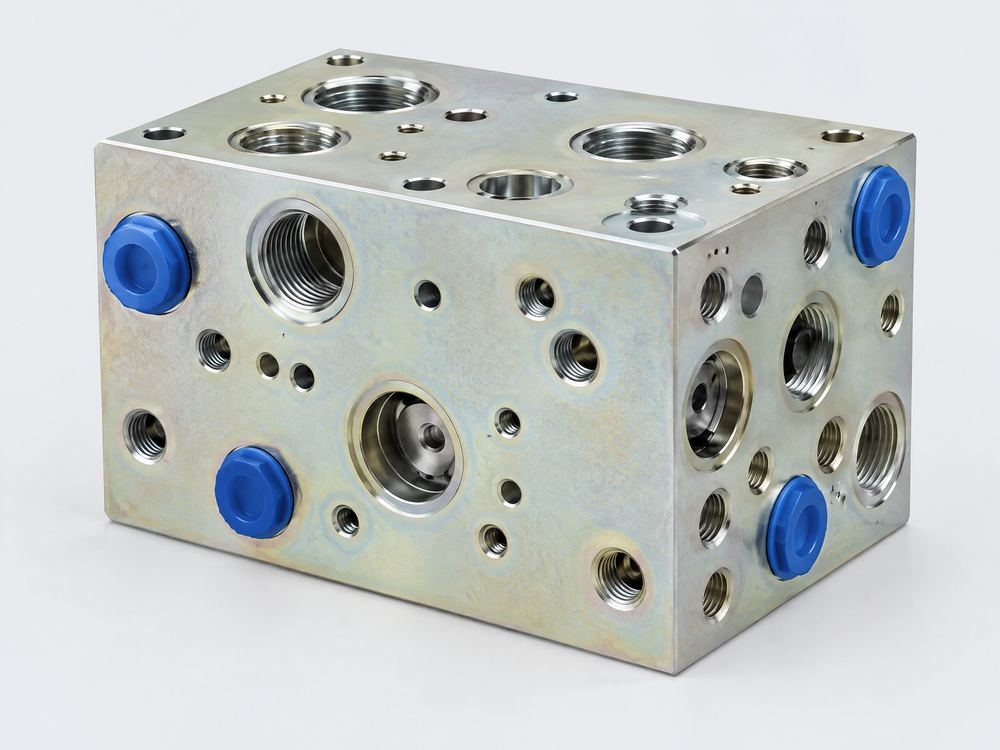
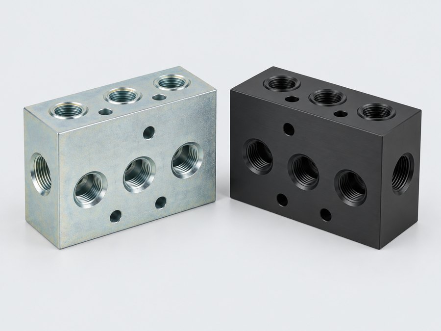
We source every hydraulic manifold made to your drawing – control blocks, valve blocks and subplates in steel, free-cutting steel or aluminium – in series from factories in China. What matters are burr-free bore intersections, dimensionally accurate valve cavities and clean channels; that is exactly what we focus the inspection plan and acceptance on.
- Control blocks in steel and aluminium
- Cartridge cavities to ISO 7789
- Pressure testing and residual contamination analysis
- Based in Jena since 2011
- Selected partner factories in China
- One contractual partner in Germany
- Pre-shipment inspection included
Control blocks and valve blocks: what matters
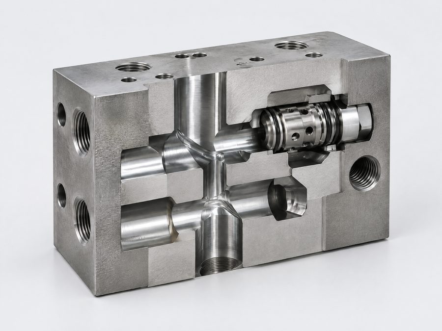
A hydraulic manifold looks simple, but it is a precision part: dozens of intersecting bores, valve cavities with tight fits and sealing faces with low roughness. Defects often only show up on the test bench – as leakage, a sticking valve spool or particles in the system.
Sourcing from China pays off mainly for recurring series blocks with a stable drawing, e.g. for mobile hydraulics, lifting equipment or power unit construction. For one-off blocks in special-purpose machinery, the short route to a regional manufacturer is usually more economical.
Technical specifications: hydraulic manifolds made to drawing
| Feature | Specification |
|---|---|
| Materials | Steel S355J2 (1.0577), C45 (1.0503), free-cutting steel 11SMnPb30 (1.0718), continuous cast iron EN-GJS-400-15 or EN-GJL-250, aluminium EN AW-6082 T6 and EN AW-2007 |
| Part weight / size | From small valve blocks from approx. 0.2 kg up to large control blocks with edge lengths of up to approx. 1,000 mm; larger blocks on request |
| Tolerances | Valve cavities to manufacturer or ISO 7789 specification (typically H8–H9), bore positions ±0.1 mm, other dimensions ISO 2768-mK, flatness of mounting faces typically 0.01–0.02 mm |
| Surface finish / post-processing | Sealing faces Ra 0.8–1.6 µm; zinc electroplated or zinc-nickel with Cr(VI)-free passivation, electroless nickel, anodised (aluminium); thermal or electrochemical deburring |
| Quantities | No fixed minimum order quantity – whether sourcing pays off depends on the block, quantity and machining effort; talk to us. One-off blocks are usually cheaper from a regional supplier |
| Inspection | Dimensional report, thread and cavity gauges, pressure test to your specification, residual contamination analysis to ISO 16232 / VDA 19.1, coating thickness, 3.1 material certificate |
| Lead time | First samples in approx. 3 weeks at best, usually longer – up to approx. 10 weeks depending on complexity; series production approx. 4–8 weeks depending on quantity and complexity (production time only), plus transport (sea freight approx. 30–45 days) |
| Data for your enquiry | 3D model (STEP) and drawing with bore plan, port standard, valve cavities with type designation, operating and test pressure, cleanliness requirement, surface finish, annual volume |
Materials for hydraulic manifolds
The choice of material depends on operating pressure, quantity and environment.
| Material | Operating pressure (guideline) | Advantages | Limitations |
|---|---|---|---|
| EN AW-6082 T6 | up to approx. 210–250 bar | Light, easy to machine, can be anodised | Lower strength at threads, more generous wall thicknesses needed |
| EN AW-2007 | up to approx. 250 bar | Excellent machinability, short chips | Contains lead (observe RoHS), poor anodising results |
| 11SMnPb30 | up to approx. 250–315 bar | Fast machining, cost-effective | Lower toughness, contains lead |
| S355J2 / C45 | up to approx. 350–420 bar | High strength, readily available | Longer machining time, corrosion protection required |
| EN-GJS-400-15 continuous cast | up to approx. 315 bar | Pressure-tight, easy to machine, vibration-damping | Microstructure inspection required, material certificate important |
Design guidelines for hydraulic manifolds made to drawing
Designate ports unambiguously
ISO 6149-1 (metric with O-ring), ISO 1179-1 (G thread) and ISO 11926-1 (UNF) are not interchangeable. State the standard and size for each port in the bore plan.
Cartridge cavities with type designation
Specify valve cavities to ISO 7789 or to the manufacturer’s catalogue with the exact designation. The factories produce them with form tools; a non-standard contour means a special tool.
Check bore intersections
Channels should meet with sufficient overlap, not tangentially. Marginal intersections create burrs that are almost impossible to remove.
Wall thicknesses between channels
As a rule of thumb, allow at least 3–5 mm of remaining wall between high-pressure channels, more for aluminium. Define auxiliary bores with plugs or ball plugs clearly.
Mounting patterns to ISO 4401
For directional valves, reference the mounting surfaces to ISO 4401 (e.g. size 03 for NG6, 05 for NG10). Flatness and roughness of the sealing face belong on the drawing.
Burr-free condition and cleanliness to ISO 16232 / VDA 19

Loose burrs and chips are the most common cause of failures in new hydraulic manifolds. Without a clear specification, “visibly burr-free” applies – which is not enough for proportional and servo valves.
So before the first samples we specify how deburring is done (thermal, electrochemical, high-pressure water, brushing) and which residual contamination limit applies, e.g. “largest metallic particle ≤ 400 µm” to ISO 16232 or VDA 19.1. After washing, ports are sealed with plugs and the blocks are individually packed in corrosion protection film.
Pressure testing and surface finishes
A pressure test at about 1.3 to 1.5 times the operating pressure with a defined holding time is customary; we define test medium, test pressure and holding time in the inspection plan according to your specification. Electroless nickel coats even deep bores evenly, whereas zinc electroplating hardly does – sealing faces and fits must be taken into account with both processes.
Cost drivers for control blocks
Number of bores and sides
Every side is a set-up. Blocks with bores on five or six sides cost considerably more than those with three.
Special cavities
Non-standard valve cavities require dedicated form drills and reamers – allow for one-off tooling costs.
Cleanliness class
Strict residual contamination limits mean additional deburring, washing and analyses. Be only as strict as the valve requires.
Material
Aluminium and free-cutting steel machine faster than S355 or C45. At moderate pressure, a comparison is worthwhile.
Process for hydraulic manifolds
Review the bore plan
Clarify ports, cavities, intersections and cleanliness specification.
Select the factory
Select a factory with experience in hydraulic manifolds and suitable deburring and washing equipment, obtain a quotation.
First samples
Dimensional report, pressure test and residual contamination analysis; you check the first samples – e.g. with your valves – and approve them.
Series
Series inspection plan with sampling, packaging with plugs, delivery as standard delivered to your door, duty paid (DDP), or under another Incoterm on request.
Frequently asked questions about hydraulic manifolds
Aluminium or steel for the hydraulic manifold?
Aluminium EN AW-6082 saves weight and machining time and is suitable, as a guideline, up to about 210–250 bar. Above that, or with high pressure peaks, steel such as S355J2 or C45 is the usual choice.
Can cartridge valves be supplied and fitted as well?
Yes, as an assembled assembly to your bill of materials. You decide whether branded valves or equivalent valves are used.
What does ISO 6149 on the drawing mean?
ISO 6149-1 describes ports with metric threads and O-ring sealing. The port has a defined counterbore for the O-ring; a thread alone does not meet the standard.
How is cleanliness verified?
By a residual contamination analysis to ISO 16232 or VDA 19.1: flushing the channels, filtration, gravimetric and microscopic evaluation of the particles.
Is a cast blank worthwhile instead of solid material?
For large control blocks with many cavities and high quantities, a cast blank can save material and machining time. Pressure tightness and microstructure must then be checked particularly carefully.
Related part types
Enquiry: Hydraulic manifolds made to your drawing
Upload your drawing and 3D model, tell us the quantity and your deadline – we check feasibility and get back to you with questions or a quotation.
- Technical clarification before the request for quotation
- Quotations from audited partner factories
- One contact person in Germany
- Non-disclosure agreement (NDA) in advance on request
Prefer to call? 03641 9286337 · Mon–Fri 8 am–6 pm (CET)