
Home › Custom parts › Stamped & deep-drawn parts
Stamped parts and deep-drawn parts made to drawing in series
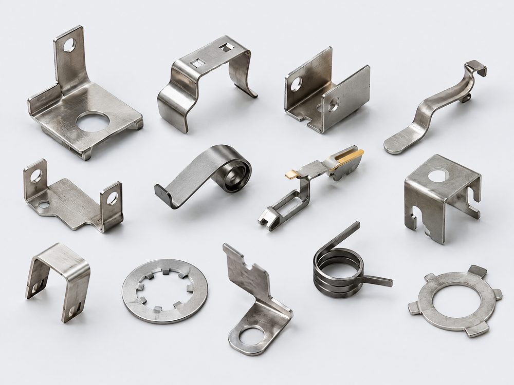
We source stamped parts, stamped-and-bent parts and deep-drawn parts made to your drawing – produced in series with a dedicated stamping die, mainly in China. This is particularly attractive for recurring demand for contacts, tabs, brackets or drawn cups, where the unit price counts and the tool pays for itself over the quantity.
- Progressive, transfer and fineblanking dies
- Tooling costs calculated against quantity
- Tolerances to DIN 6930-2
- Based in Jena since 2011
- Selected partner factories in China
- One contractual partner in Germany
- Pre-shipment inspection included
Stamped and formed parts: when a tool pays off
A stamping die cuts and forms a part in one or a few press strokes – for small parts in a fraction of a second. This involves one-off tooling costs, which are in the low four-figure euro range for simple blanking dies and in the five-figure euro range for progressive dies (guideline values).
The threshold compared with laser-cut and bent parts is therefore the quantity: for small annual volumes, laser-cut sheet metal parts are usually cheaper; for large series, the stamped part is practically unbeatable on unit price. In between, a break-even calculation helps, which we carry out with you based on actual quotations. We have no fixed minimum order quantity.
Tooling prices in China are usually well below European levels. Why that is and what you should look out for with tools is explained in the guide Tooling costs in China.
Technical specifications: stamped parts and deep-drawn parts
| Feature | Specification |
|---|---|
| Materials | Cold-rolled strip DC01–DC06, spring steel C75S (1.1248), stainless steel 1.4301 / 1.4310, copper Cu-ETP, brass CuZn37, bronze CuSn6, aluminium EN AW-1050A / 5754; pre-coated strip (galvanised, tin-plated) |
| Part weight / size | Sheet thicknesses usually 0.1–6 mm, thicker on request; parts from a few millimetres up to large pressed and drawn parts – large presses over 1,000 t are also available in the network; larger parts on request |
| Tolerances | Stamped parts to DIN 6930-2 (f or m); cut contours approx. ±0.05–0.1 mm; fineblanking approx. ±0.01–0.03 mm with an almost fully sheared (smooth) edge |
| Surface finish / post-processing | Vibratory finishing/deburring, zinc electroplating with passivation, zinc-nickel, tin-plated, nickel-plated, heat treatment (hardening, quenching and tempering for spring parts) |
| Quantities | No fixed minimum order quantity – whether sourcing pays off depends on the part, quantity and tooling costs; talk to us; call-off orders possible |
| Inspection | First article inspection report (FAIR / EMPB), burr height, smooth-cut proportion, wall thickness for drawn parts, SPC on functional dimensions, spring force measurement, 3.1 material certificate |
| Lead time | First samples in approx. 3 weeks at best, usually longer – up to approx. 10 weeks depending on complexity; series production approx. 4–8 weeks depending on quantity and complexity (production time only, plus transport); toolmaking included in the first sample lead time |
| Data for your enquiry | Drawing with tolerances and burr side, 3D model (STEP), material with condition (e.g. hardness), surface finish, annual volume and duration, required packaging (bulk, layered, on carrier strip) |
Stamping die variants: progressive die, transfer, fineblanking, deep drawing
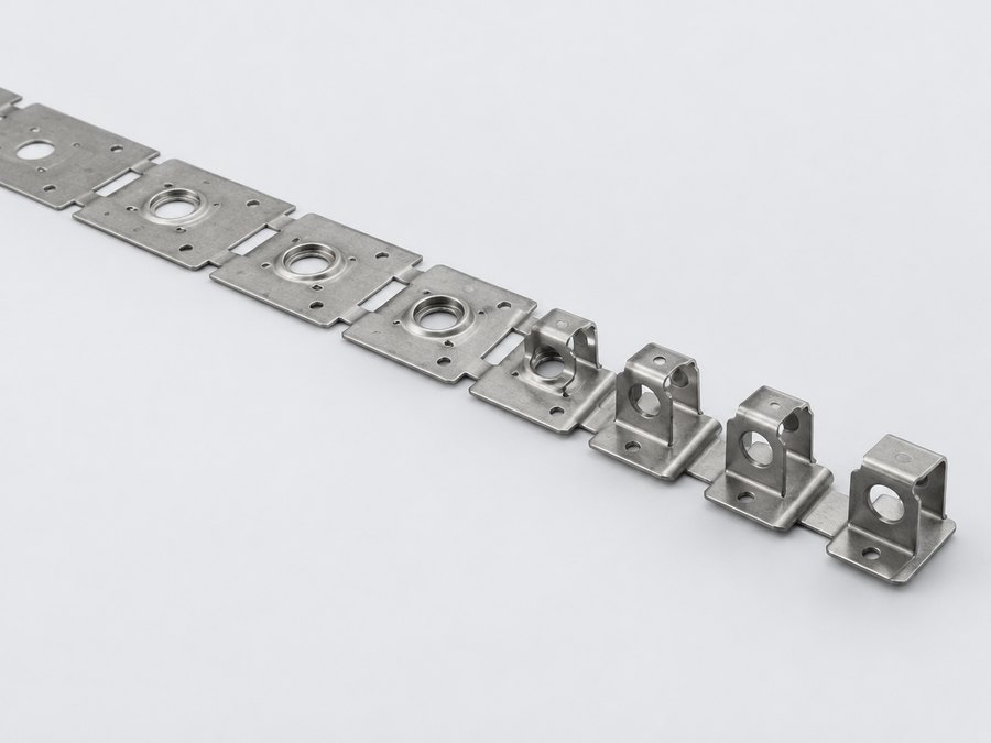
The tool concept determines unit price, tolerance and tooling costs. The ranges are guideline values.
| Process | Typical parts | Quantity | Tooling costs | Special feature |
|---|---|---|---|---|
| Simple blanking die | Washers, flat tabs | small to medium series | low | One operation, bending separately |
| Progressive die | Stamped-and-bent parts, contacts, brackets | large series | medium to high | Several stations on the strip, very low unit price |
| Transfer die | Larger formed parts, drawn parts | large series | high | Part is transported freely between stations |
| Fineblanking | Gear segments, levers, pawls | large series | high | Smooth, square cut edges without rework |
| Deep drawing | Cups, sleeves, lids, trays | medium to large series | medium to high | Seamless, several draws depending on the drawing ratio |
Design guidelines for stamped-and-bent parts
Hole diameter and web width
Hole diameter at least 1 × sheet thickness, for stainless steel rather 1.5 × t. Webs between holes and to the edge also at least 1–1.5 × t, otherwise the punch breaks or the web deforms.
Specify the burr side
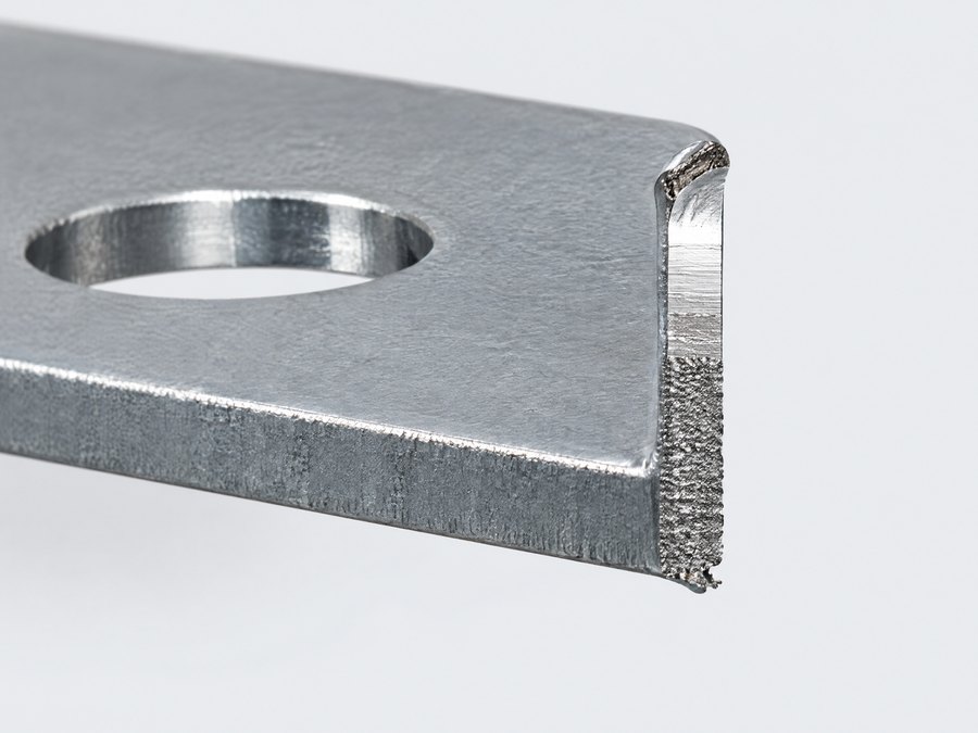
Every stamped part has a smooth-cut side and a burr side. State on the drawing on which side the burr may be, and limit the burr height – e.g. ≤ 10 % of the sheet thickness.
Bending and rolling direction
Place bends across the rolling direction wherever possible. With spring steel and hard tempers, bends parallel to the rolling direction crack easily.
Distance from hole to bend
Holes at least 2 × t + bend radius away from the bend line; otherwise have them pierced in the tool only after bending – which costs an extra station.
Avoid sharp internal corners
Internal radii of at least 0.5 × t on cut contours significantly extend tool life. Sharp corners are breaking points on the punch.
Drawn parts with radii and draft
Bottom radius in deep drawing approx. 3–5 × t, draw edge radius approx. 5–10 × t. Vertical walls and sharp bottom edges require additional draws or restriking stations.
Deep-drawn parts: drawing ratio and number of draws
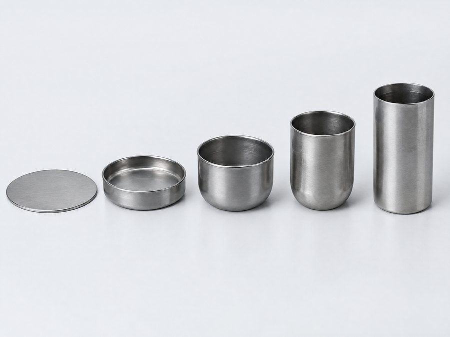
The drawing ratio β is the ratio of blank diameter to punch diameter. In the first draw, values of about 1.8–2.0 are achievable with deep-drawing steel DC04 and stainless steel 1.4301; in subsequent draws only about 1.2–1.3. A cup with a diameter of 40 mm and a depth of 60 mm therefore needs several draws – every station increases tooling costs and cycle time.
Stainless steel work-hardens strongly during drawing. For deep parts, intermediate annealing between draws is necessary, which increases cost and lead time. If the function allows, it is worth asking whether a ferritic stainless steel such as 1.4016 or a coated deep-drawing steel would suffice.
- Wall thinning at the bottom edge typically 10–20 % – state the minimum wall thickness on the drawing
- Earing at the rim: the rim is usually trimmed afterwards – tolerance the trim height
- Draw marks due to tool wear: mark visible surfaces and define limit samples
Burrs, cracks, dimensional drift: typical defects in stamped parts
Growing burr
As the stroke count increases, the cutting edges become blunt and the burr grows. Include burr height as an inspection feature in the series inspection plan and agree regrinding intervals for the tool.
Springback
Higher-strength steels, stainless steel and spring strip spring back after bending. Measure angles on the first samples and have the tool corrected before series production is approved.
Cracks in drawn parts
Causes are too high a drawing ratio, incorrect lubrication or material with poor deep-drawing properties. Require the material grade (e.g. DC04 instead of DC01) and a certificate.
Uncontrolled tool changes
Tools are repaired or copied without the customer knowing. Agree tool identification, a tool list and mandatory approval for changes – we monitor this as part of our quality assurance.
Tooling costs vs. quantity: how to calculate correctly
Never compare the unit price alone. Spread the tooling costs over the expected total quantity and add freight, customs duty and inspection effort. A stamped part at €0.08 with a €15,000 tool is more expensive than a laser-cut part at €0.30 at 20,000 pieces per year over three years – at 200,000 pieces per year it is far superior.
With us, ownership of the tool passes to you once it has been paid in full; it stays at the factory for production and is marked accordingly – the arrangement is set out in the quotation. On request, we organise relocation to Germany or Europe. Also clarify how many strokes the tool is to achieve: progressive dies with carbide cutting elements usually manage several million strokes, tools made of tool steel considerably fewer.
- Multiple parts per stroke: two or four parts per stroke halve or quarter the press time
- Material utilisation: optimise the strip layout – scrap is a major cost factor with copper alloys
- Open up tolerances where possible: fineblanking only if the cut edge is a functional surface
- Surface finish on the strip: pre-tinned or pre-galvanised strip instead of plating individual parts, if unprotected cut edges are acceptable
Process: from stamping die to series production
Feasibility and strip layout
The factory creates the strip layout or draw sequence; we check it with you against the drawing.
Toolmaking
Tool design for approval, then construction and try-out – with photos and progress reports.
First samples from the series tool
Measurement report covering all features, burr height, material certificate; documented as a first article inspection report on request.
Process approval
Series inspection plan with SPC for functional dimensions, tool maintenance plan, packaging specification.
Series delivery
Delivery on call-off, monitoring of burr and dimensional drift over the tool life.
Frequently asked questions about stamped and deep-drawn parts
Who owns the stamping die?
Once paid in full, ownership of the tool passes to you. It stays at the factory for production and is marked accordingly; the arrangement is set out in the quotation. On request, we organise relocation to Germany or Europe.
What is the difference between stamping and fineblanking?
In conventional stamping, only part of the cut edge is smooth; the rest is the fracture zone. Fineblanking uses a V-ring (impingement ring) and counter-pressure to produce an almost completely smooth, square cut edge – necessary for functional surfaces such as tooth flanks.
How high may the burr on a stamped part be?
You define that. Without a specification, there will be disputes at inspection. It is common to limit it to a fraction of the sheet thickness; critical edges are vibratory finished.
Can an existing tool be relocated from Europe to China?
In principle yes, if it fits the factory’s press. A new tool is often more economical, because transport, try-out and adaptation would otherwise be expensive. We clarify this on a case-by-case basis.
How many draws does my deep-drawn part need?
That depends on the drawing ratio. As a rule of thumb, the first draw achieves a ratio of blank diameter to punch diameter of around 2.0, every further draw only about 1.2–1.3.
Are stamped parts delivered loose or arranged?
Both are possible. For automated assembly, layered parts or parts on carrier strip make sense; bulk is cheaper but parts can tangle or bend.
Related part types
Enquiry: Stamped & deep-drawn parts made to your drawing
Upload your drawing and 3D model, tell us the quantity and your deadline – we check feasibility and get back to you with questions or a quotation.
- Technical clarification before the request for quotation
- Quotations from audited partner factories
- One contact person in Germany
- Non-disclosure agreement (NDA) in advance on request
Prefer to call? 03641 9286337 · Mon–Fri 8 am–6 pm (CET)